NEW REPAIR GUIDES

FORGOT YOUR DETAILS?

Hoover Heat Pump Tumble Dryer DXH10A2TCE-80 Can’t run the self diagnosis

by / Monday, 08 February 2021 / Published in

Hi,I replaced the main board for my Hoover tumble dryer. It was advised to run the self diagnosis test before taking the dryer to use after replacing the main board. However, the machine won't do that even though I try doing it following the intructions that came with the new main board: -Turn the program selector knob 2 steps in clockwise sense from the OFF position.-Push and hold the first option button to the left of the display. That should turn ALL LEDs on and the display should show the last thtee digits of the Eeprom Code in memory. THAT DOESN'T HAPPEN.-Within 3 seconds from the moment all LEDs are ON, push the Start/Pause button. But as tje LEDs won't go ON, it doesn't help to push the button either.

Manu Lehtinen


Paul answersI will try and help with your Hoover Heat Pump Tumble Dryer DXH10A2TCE-80 problem.

Paul answers
I will put the test TEST ROUTINE PROCEDURE below for you


If you want to support the site please mark us to your favourites, also I would be grateful if you would subscribe to our social media channels as this really helps my site and keeps us going.

YouTube. http://www.youtube.com/user/howtorepair
Facebook. https://www.facebook.com/how.to.repair.appliances
And if we really helped you save money you can always click on the Buy Paul a Beer page

Test Activating

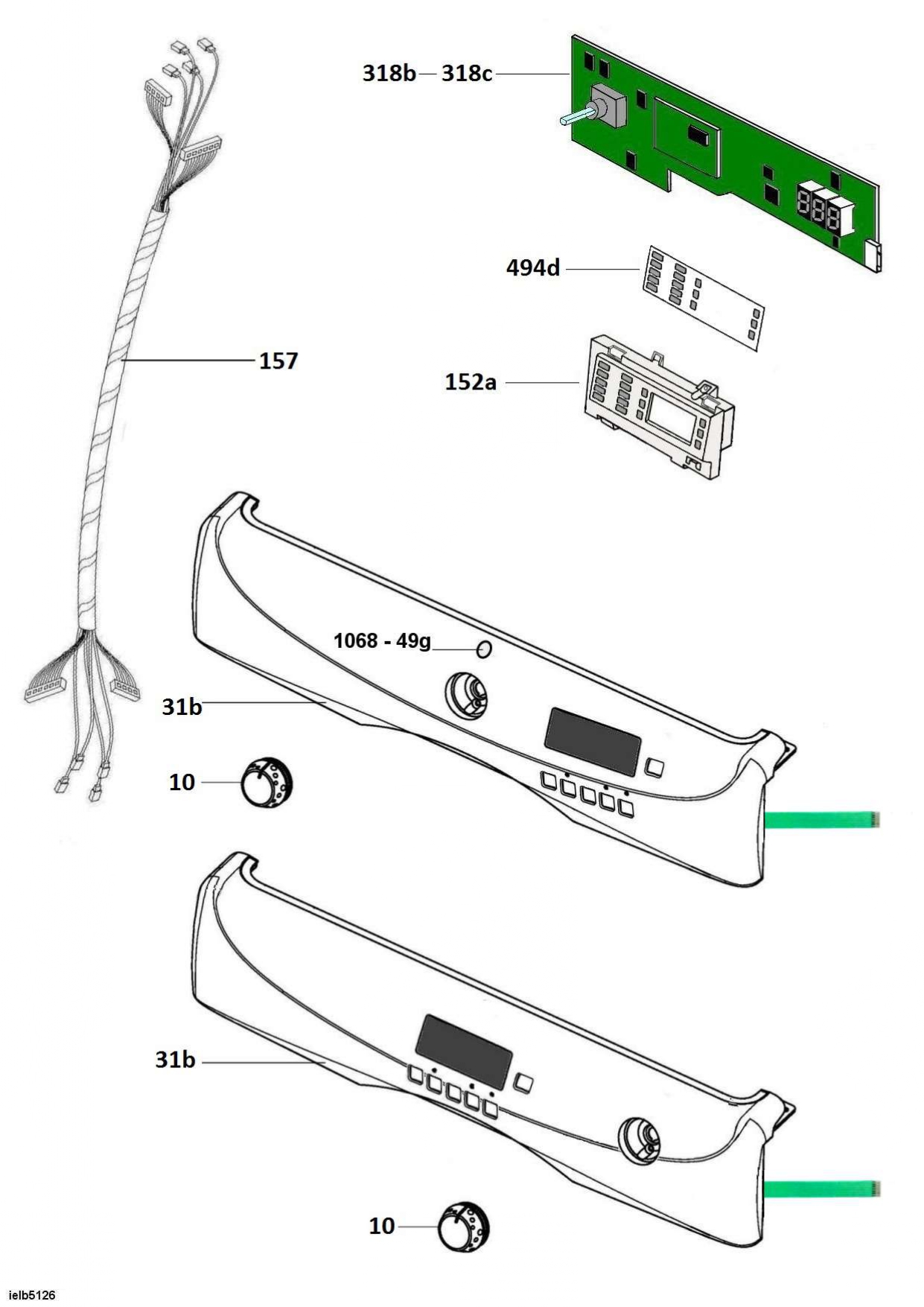
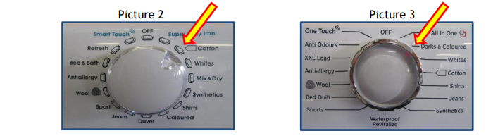
Picture 2 shows the knob in the Candy version while Picture 3 shows the knob in Hoover

version.

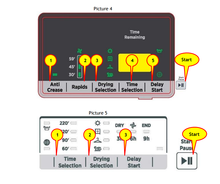
Picture 4 shows the version of the machine with a display, if you have a machine with an LED

version, refer to Picture 5.

BE AWARE: It should be noted that the activation phase (of the factory test) has a very short

duration, for that reason you need to pay attention to each stage.

When the test ends without displaying errors it does not mean that all electromechanical /

electronic components present on the machine work properly. For some components a visual

check is required, for others it is necessary to check that the corresponding current value,

shown on the power meter is correct. If in doubt, it is recommended to repeat the test

focusing on the execution of the specific phase.

TEST INITIALIZATION:

  • Open the porthole door and visually check that the TUB IS EMPTY, close the porthole

door.

  • Starting from the OFF position, turn the knob clockwise to the second program as shown

in picture 2 for Candy version and in picture 3 for Hoover version.

  • Within 3 seconds, press the key with Ref. 1 in pictures 4 & 5. Only in cases where the

model has a display the number 888 will show (all the leds are lit up).

  • Press the Start key, in cases the model has a display the last three Eeprom code figures

will be shown on the electric module.

  • In cases where the model has a display press in sequence keys 2, 3, 4 and 5 while in

case of a led model press in sequence keys 2 and 3.

  • After last key has been pressed the test routine procedure will start.

Be aware of the key sound and leds that turn off every time a key is pressed because it

means that the keys are working correctly.

At the end of the test, if all the LEDs are flashing or the display shows the last three digits of

the Eeprom where a display is present, this means that the test has completed normally.

Open the porthole door to stop the drum rotation, this gives the opportunity to check that the

micro switch works correctly. Turn the knob to the OFF position.

3) Description of the steps of the test routine

Phase 1: The drum rotates clockwise and on the appliance with a display it shows the text “riG”.

In case of a heat pump appliance both motor and compressor are checked, note the

multimeter will increase from about 1.6A (Compressor absorption + Motor absorption).

In case of an heater appliance both motor and heating elements are checked, note the

multimeter will increase from about 8.9A (Compressor absorption + Motor absorption).

Phase 2: Checks the drum rotates anticlockwise. The drum rotation is to the left and on the

appliance with a display it shows the text “LEF”.

Phase 3: Drain Pump is checked. This check is done even if the machine does not have a pump.

On the appliance with a display it shows the text “dPU”.

Phase 4: This phase is only for heat pump machines. The fan operation is checked. This check is

done even if the machine does not have a fan. On the appliance with a display it shows

the text “Fan”.

Phase 5: The NFC function is checked and password is written so that it can only be rewritten by

the APP Service. On the appliance with a display it shows the text “nFC”.

Phase 6: At the end of the test routine on the appliance with a display it shows the text “Dor”

(door) while the led labelled END will turn on the led machines. The drum keeps on turning

clockwise.

Phase 7: Open the door to stop the rotation of the drum, this gives the opportunity to check the

micro switch works correctly. If the door is not opened within 3 minutes an error will

occur and on the appliance with a display it shows the text “ERR”.

Phase 8: End of the test sequence.

NOTE: TURN THE SELECTOR KNOB BACK TO THE OFF POSITION AND UNPLUG THE MACHINE. LET

THE MACHINE POWER OFF FOR AT LEAST 30", this is to be sure that the test procedure has

been reset. The appliance with these power cards remain in a "standby" condition (electrically

powered on) even if the selector knob is in the OFF position.

UK Engineers only: When connecting the appliance for the test routine use your Energine meter

and test with your mulitmeter. You DO NOT need to use the Shuko patch cord.

Cuore NFC electric module
ERROR CODE MOST PROBABLE REASON FOR THE ERROR CODE
E03 Tank is full of water and has to be emptied.
E05 Front NTC sensor is either short circuit or open circuit. Check front NTC sensor and/or
wiring.
E07 Alarm, filter occluded, This error can only appear after the end of a cycle. The filter is
occluded because of fluff presence, the correct ventilation is not allowed. Clean the filter.
E08
Thermo fuse intervention. Replace the thermo fuse and check that ventilation circuit is
clean, check the wiring.
E10 Missing communication between "Cuore" Electric Module and Display Electric Module and/or
Wiring.
E11
In the rear part of condenser the temperature is too high. Check that all ventilation ducts
are clean, check that ventilation system is working well. Check the condenser, the motor,
the fan could be broke/blocked.
E12 Pressure switch doesn’t work. Check the pressure switch and/or wiring. Check that the air
trap is clean.
E13 Compressor NTC Probe is either Short Circuit or Open Circuit. Check the compressor NTC
probe and/or wiring.
E14
Rear NTC Probe is either Short Circuit or Open Circuit. Check the rear NTC probe and/or
wiring.
E15 Main board not programmed. Program the main board.
E19
It is not possible to use NFC tag for any actions until the next POWER ON/OFF. (switch off
and switch on)
E21
Heater control relay on the “cuore” electric module is not working. High temperature has
been reached – Thermo Fuse worked. Check the thermo Fuse, and the wiring. Check that
both the ventilation circuit and ventilation ducts are clean and duct is not obstructed.
Replace the “cuore” electric module only in the case that the heater command relay is
faulty.
E22
Compressor control relay on the “cuore” electric module is not working. Check the
compressor and compressor wiring/connections. Replace the “cuore” electric module only
in the case that the compressor command relay is faulty.

Common Hoover Heat Pump Tumble Dryer DXH10A2TCE-80 faults with links to the right repair guide

I have included a lot of videos in the links below on these tumble dryers to assist you in repairing your tumble dryer; I have also included an exploded diagram of your machine with all the parts that you need listed below that just click on the relevant and it will take you to a search result

  1. No heat

This is the most common fault on tumble dryers.

Vented dryers: this can be a fault with the thermostats, heater, or on some occasions, it might be the timer or the relay on the printed circuit board.

Condensor dryers: this might be any of the above but you also have a condenser plate that collects the water and then is either pumped to the collection tray or flows into a tank. Check pump unit and float switches.

Heat pump dryers: these are much more complicated they use a refrigeration prosses to heat the cloths and use the cooling side to condense the water for collection. Check compressor is running, check NTC sensors and check filters, and also that it has the right amount of refrigeration gas (normally only done by an engineer)

  1. Drum not turning

This will stop the dryer from drying. You may have to replace a faulty belt or in other cases, look at the motor, motor capacitor, or the jockey wheels. Again there are relays on printed circuit board types that can go faulty.

  1. Not starting

Whilst, not a common problem, you may have a faulty door switch, starter relay if fitted, or can be start button or PCB.

  1. Noisy Machine

This is usually caused by faulty bearings, jockey wheels or worn felt pads. The motor can get dust build up in the bearings, also the fan blades can distort in shape and make noise rubbing the housing.

  1. Water leaks.

This can be a simple as the water tank (in a condenser tumble dryer) has not been emptied, or not placed back into the housing correctly. The condenser plate can need cleaning. The pump unit might not be working. Or the ducting system can be clogged with fluff etc. See servicing tumble dryer.

  1. Tumble dryer reports a fault code or error code.

Error codes can be on the display or given in certain lights flashing sequences. Tumble dryer fault codes are not universal but may only point you or an engineer in the right direction they are not 100% accurate they are only that for guidance. Your owner’s manual may help you identify the problem and even suggest a fix. In other cases, you’ll need an engineer to trace the fault. Don’t be tempted to ignore a fault code, even if the dryer seems to be functioning normally. Some codes are ‘early warning signs’ and fixing the machine at an early stage could save you time and money in the long run.Contact us with the full model number and detailed description 

If you need any further assistance please feel free to contact me​. all the best Paul​.

photo  
Paul Charmbury
Appliances Engineer
youtube facebook google+ beer

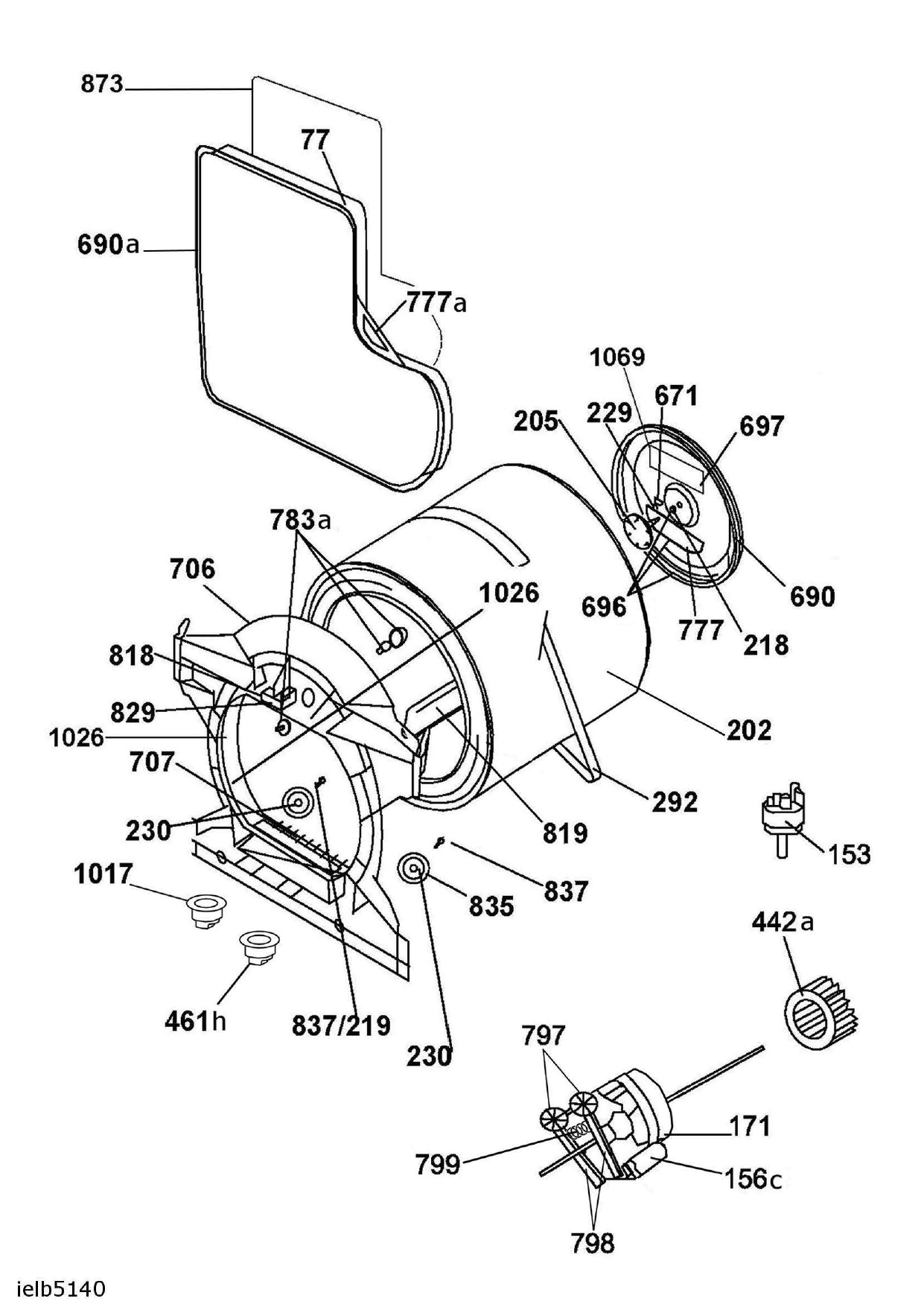
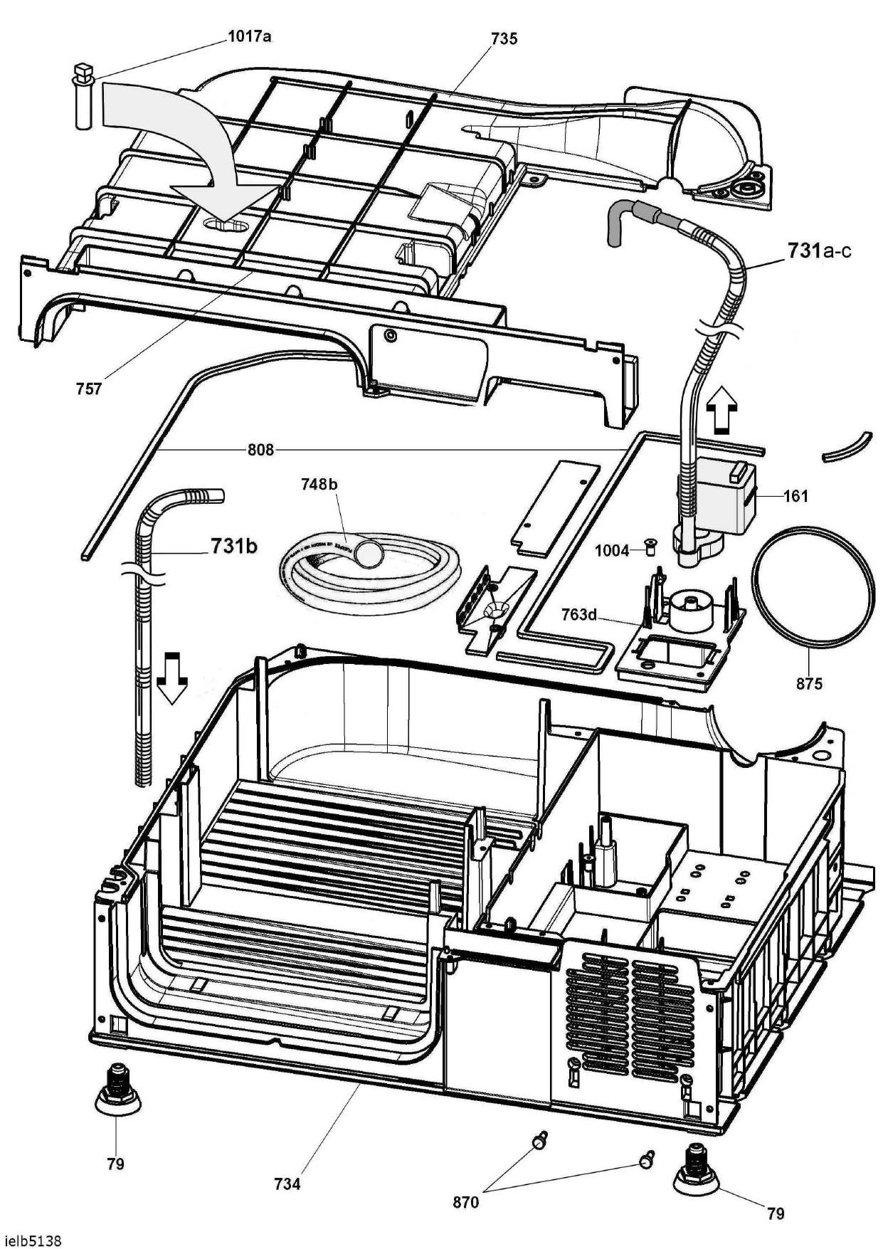
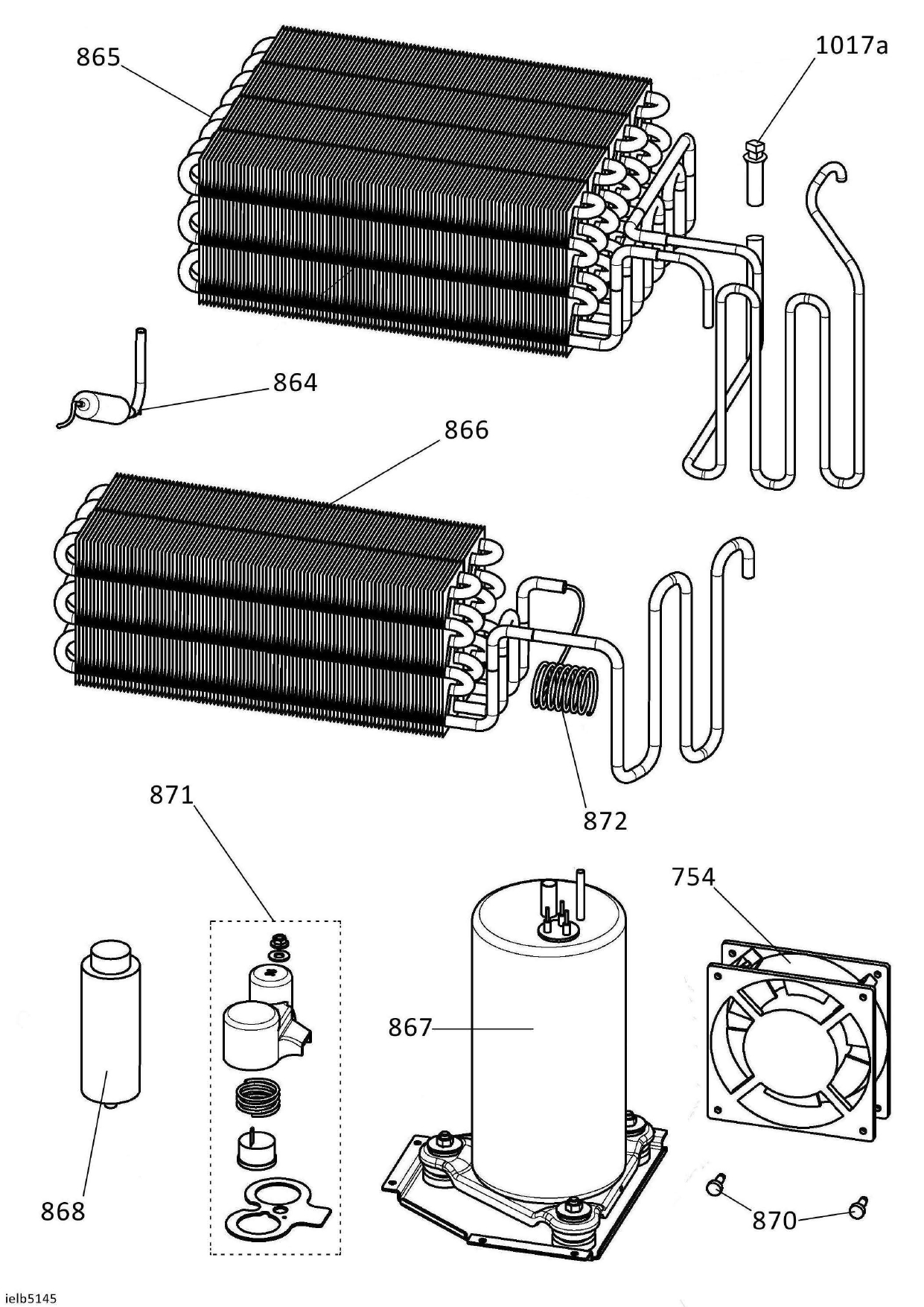
Match your part for Hoover Heat Pump Tumble Dryer DXH10A2TCE-80 and use reference number in list below and click on the link to your part

Reference Part Number Description
10 40009129 Timer/select. knob
31b 40011637 Control panel with Sensor
48 40010677 R/H side frame
48a 40010678 L/H side frame
49 40004597 Top rear frame
49g 41041380 Trade mark plate
51 40004601 Work top
60 40009040 Hinge
63 40006231 Door glass
67 40010996 Door with trim
67c 40010550 shoe stand
77 40011864 Rear panel
79 40002885 Foot
82 40009192 Door panel
88 40008589 Front panel
131a 92470020 Hose clip
152a 40010529 Light guide support
153 28375043 Pressure switch
156 41039164 Capacitor 7 MF
157 40011151 Harness
161 40005021 Pump
164 91200489 Anti jamming filter radio
171 40011078 Main motor
202 40009125 Drum
205 40006362 Drum shaft assy
218 03210179 Bearing
225a 40005405 Gasket
229 24721202 Circlip
230 40004306 Bearing clamp
271 40005393 Door gasket
280 40009775 Hose clip
292 40001012 Drive belt
318b 49040252 Electronic control PCB - NFC -Programmed
318c 49041619 Electronic NFC pcb - Not programmed
440a 46004464 Scroll seal
441 40006774 Cover
442a 40006726 Rear fan
461h 41014595 drying probe seal
491c 91200201 Mains cable x UK
494d 40010528 Light Guide - Digital Display
520 40006928 Door coupler
607 40006220 Pin for hinge
631 40006586 Stopper
643a 41041381 Handle plate - profile
671 03610428 Washer
690 40006246 Rear sealing felt
690c 40010756 Seal motor/water duct
697 40006724 Heater support disk
706 40010750 Front ring assembly
706a 40011352 Duct side filter
707 40005584 Filter for carter
731a 40006359 Delivery pipe (Water delivery)
731b 40006360 Flow pipe (Water drain)
734 40006721 Container
735 40006722 Cover
745 40009144 Kickplate assy
748 03320032 Tube
754 40006728 Ventilator
756 23715194 Spring
757 40003315 Gasket
763d 40006727 Reservoir top cover
764 40004815 Gasket
766 40009648 Water container assy
777 40004157 Heater gasket
797 40004610 Beltightening pulley
799 40001026 Belt tighteningb spring
804 40009167 Hinge fixing upper bracke
808 40006767 Capacitor contain gasket
819 40009121 Drum scowel
822 40010003 Innerdoor assy
826 40004091 Door hook
835 40004307 Drum support wheels
840a 40008358 Floating
864 40011156 Filter Assy
864c 40010703 Service Pipe Accumulator
865 40006763 Condenser
866 40006764 Evaporator
867 40010153 Compressor
868 41041497 Run capacitor
870 41020195 Screw
871 40010154 Terminal Compressor Kit
872 40006807 Capillary hose
873 40008116 Rear insulating
874 40006731 Sponge filter
874b 40006730 Plastic frame for sponge filter
874c 40006911 Sponge filter fixing Pin
875 40006762 Ring seal
998a 40011659 Eeprom File NFC
999 41045070 Electrical diagram
1004 40005153 Flow restrictor
1017 41022106 NTC probe
1017a 41035594 NTC probe
1026 40011691 Front felt
1069 40006796 Gasket

full list of spare parts for Hoover Heat Pump Tumble Dryer DXH10A2TCE-80

Our How-to-repair stores

Current page 1 Total pages 0
24h technical help answers

Questions on faults in the comments will not be answered. Please use the contact us form instead.

TOP